
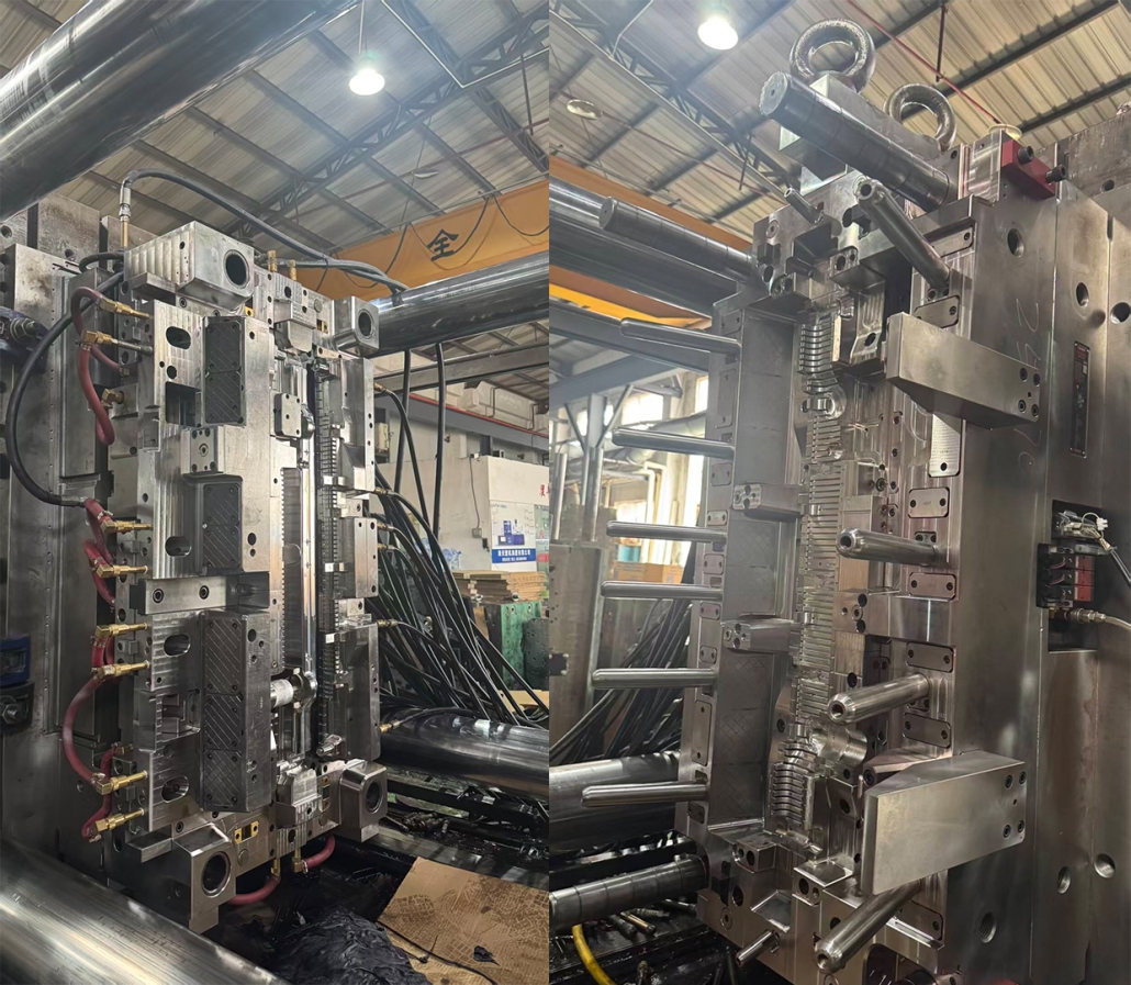
Plastic Injection Mold for Automotive Bottom Tank
/in News/by administratorPlastic injection mold for automotive bottom tank must produce a component that can withstand coolant pressure, high engine-compartment temperatures, vibration, and repeated thermal cycling. The molded tank also needs accurate sealing surfaces, stable hose connections, and consistent dimensions for assembly with the aluminum radiator core.
WIT MOLD develops automotive injection molds for radiator tanks, cooling system components, engine-compartment parts, air-conditioning parts, and other under-the-hood plastic products. From DFM analysis and mold-flow evaluation to machining, mold trials, and sample inspection, each project is developed around the customer’s material, production volume, molding machine, and validation requirements.
What Is an Automotive Radiator Bottom Tank?
An automotive radiator bottom tank, also called a radiator lower tank or radiator end tank, is a molded plastic component connected to the radiator core. It guides coolant through the cooling system and may integrate:
- Coolant inlet or outlet connections
- Drain ports
- Sensor interfaces
- Mounting brackets
- Locating features
- Reinforcement ribs
- Sealing flanges
- Transmission cooler connections
It is different from a coolant expansion tank or overflow reservoir. These components may all belong to the automotive cooling system, but they have different structures, pressure requirements, and mold designs.
Key Requirements for a Radiator Tank Injection Mold
Accurate Sealing Surfaces
The sealing flange must maintain the required flatness, profile, and wall thickness so the plastic tank can be assembled securely with the radiator core and gasket.
Common risks include:
- Flange warpage
- Flash on the sealing edge
- Uneven gasket compression
- Sink marks near ribs
- Dimensional changes after cooling
- Parting-line mismatch
The parting line, gate location, cooling system, and ejection layout must therefore be designed around the critical sealing area.
Controlled Warpage
Automotive radiator tanks often contain long walls, deep ribs, hose connectors, bosses, and different wall thicknesses. These features can create uneven shrinkage, especially when glass-fiber-reinforced materials are used.
Mold-flow and warpage analysis can help evaluate:
- Filling balance
- Weld-line position
- Air traps
- Packing pressure
- Fiber orientation
- Cooling balance
- Shrinkage
- Expected deformation
Early analysis helps reduce repeated tool modifications after the first mold trial.
Complex Side Actions
Coolant connections, drain ports, clips, and mounting structures may create undercuts that cannot be released through straight ejection.
Depending on the part design, the mold may require:
- Hydraulic or mechanical slides
- Angled cores
- Lifters
- Replaceable inserts
- Collapsible or removable cores
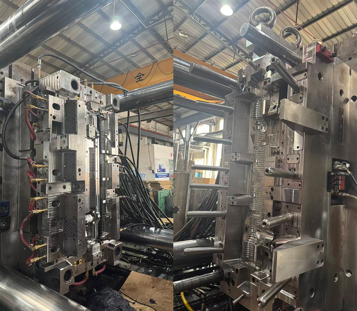
The mold shown in this project uses multiple side-action mechanisms and detailed inserts to form complex radiator tank features while maintaining production accuracy.
Material Considerations
Radiator bottom tanks are commonly molded from reinforced engineering plastics such as heat-stabilized and hydrolysis-resistant PA66 with glass fiber.
Typical material directions include:
- PA66-GF30
- PA66-GF35
- Heat-stabilized polyamide
- Hydrolysis-resistant polyamide
- Customer-specified coolant-resistant materials
The selected resin must match the operating temperature, coolant type, pressure level, vehicle platform, and OEM testing requirements.
Glass fiber increases strength and dimensional stability, but it also affects shrinkage, flow direction, surface appearance, and mold wear. Gate inserts, shutoff areas, and high-flow regions should therefore use suitable tool steel and wear-resistant design.
Gate, Cooling, and Venting Design
The runner and gate system should fill the automotive radiator bottom tank evenly without creating excessive shear, weak weld lines, or unbalanced fiber orientation.
The design should consider:
- Part volume
- Wall thickness
- Resin viscosity
- Glass-fiber content
- Connector positions
- Required cycle time
- Injection molding machine capacity
Cooling channels should be arranged around the sealing flange, hose connectors, deep cavity regions, ribs, and thick bosses. Balanced cooling helps reduce deformation and improves cycle stability.
Venting is also important. Trapped gas can cause burn marks, short shots, incomplete ribs, weak weld lines, or poor connector formation. Vents should be placed near end-of-fill areas, ribs, slides, and complex intersections.
Ejection and Mold Maintenance
The molded radiator tank must be released without damaging the sealing flange, connector necks, or visible surfaces.
The ejection system may use:
- Ejector pins
- Ejector sleeves
- Stripper elements
- Lifters
- Air-assisted release
Ejection force should be distributed over structurally supported areas. Excessive force near thin walls or sealing surfaces can cause stress marks and permanent deformation.
Replaceable inserts are also recommended for high-wear or frequently modified areas, including gates, connector cores, shutoffs, vents, and product identification.
Mold Trial and Sample Inspection
A successful mold trial involves more than filling the cavity. Samples should be inspected according to their assembly and functional requirements.
Important checks include:
| Inspection Area | Main Checkpoints |
|---|---|
| Sealing flange | Flatness, profile, flash and deformation |
| Coolant connectors | Diameter, position and roundness |
| Mounting features | Hole position, clips and brackets |
| Wall and ribs | Thickness, sink marks and short shots |
| Surface quality | Burns, flow marks and weld lines |
| Dimensions | Critical datums and assembly dimensions |
| Assembly | Fit with the radiator core and gasket |
Leakage, pressure, vibration, coolant resistance, and thermal cycling should be tested according to the customer’s automotive validation standard.
Information Required for a Mold Quotation
To evaluate a new automotive radiator tank injection mold, please provide:
- 3D part file
- 2D drawing with tolerances
- Plastic material grade
- Annual production volume
- Required mold life
- Number of cavities
- Injection molding machine specifications
- Critical sealing and flatness requirements
- Testing and validation standards
- Target trial and delivery schedule
WIT MOLD can review the part design, gate strategy, warpage risk, cooling layout, side-action requirements, ejection system, and tool steel selection before mold manufacturing begins.
For a custom plastic injection mold for automotive bottom tank, submit your drawings and technical requirements to receive a DFM review and tooling quotation.